
On this page
In UNE for ArcGIS, an editor can switch between different drawing modes as they digitize a new feature. For example they can draw the straight sides of a building using the Standard (vertex) mode and then switch to the Curve drawing mode to draw a segment of a wall that is curved.
The active drawing mode button is shown in the top right hand corner of the application when in Create mode. Clicking on the button opens up a list of available drawing mode options that a user can select to use.

Configuring drawing modes
The Standard mode is automatically available with each app. Curves, Freehand, Follow, and Enter coordinates can be configured through the Drawing actions button in the builder.


The Stencils drawing mode is made available by configuring and adding the Stencils Panel to your app in the builder.
Standard (vertex) mode
Records a vertex at each click.
Curve mode
Curve mode allows a user to define the first and last vertex and the height of a curve. Note that UNE for ArcGIS does not support true curves.
Freehand mode
Freehand mode will allow a user to capture continuously whilst using a mouse or touch device.
Follow mode
Follow mode allows a user to follow along the edges of existing geometry in the map when constructing a new feature. Highlighting indicates to the user which edges is being followed, and vertices will be automatically generated along the edge.
Stencils
Stencil draw mode allows users to pick from a predefined list of stencils of which to construct the feature.
Coordinate entry
Coordinate entry allows a user to stipulate either one or multiple coordinate pairs to construct a feature. It is possible in the builder to allow a user to choose from multiple coordinate systems.
Multiple coordinates must be entered in the form X,Y,Z* separated on new lines.
This option will not show in the client for point geometry types.

Flags for Z-enabled layers
A number of information flags may show in the coordinate entry panel to assist users in understanding settings applied to the specific layer being created. The following builder/client settings will cause the following flags to appear:
- Layers which have their Z awareness in Builder set to “On the ground”.

- Layers which have Z calculation under topology settings in Builder.

- *Layers which have Z alignment set to “Same Value” under topology settings in Builder.
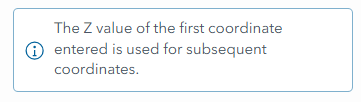
- *AND when the client Z alignment Locked (level) setting is active.
- *When the client Z alignment Locked (same offset) setting is active.
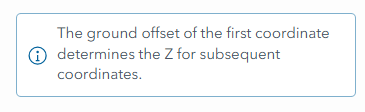
*In this setting, the single coordinate Z entry box will disappear once the first vertex is digitized during an edit. In multiple coordinate entry, any Z value entered after the first vertex will be overridden. The coordinate entry panel information icon will also update to display what the Z value is locked to whilst digitizing. It is sometimes necessary to report this value in absolute terms when working with a ground surface.
Enabling multiple coordinate systems
Please be aware that this is an app wide setting and therefore would allow users to also choose from multiple coordinate systems if using Plans functionality.
- Open the Measurements panel.

- Expand Coordinate Systems.
- Using the Add button, add a new coordinate system.
- Give the coordinate system an appropriate name and add the spatial reference ID.
